Tron Restore
From Fixme.ch
Contents
Description
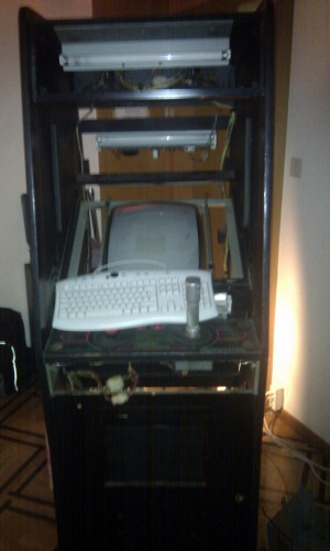
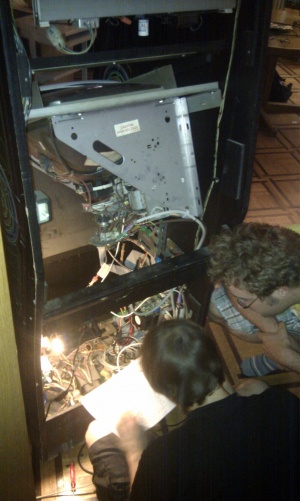
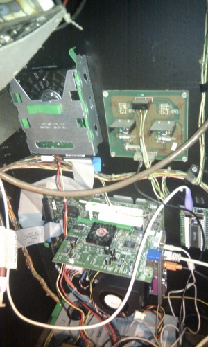
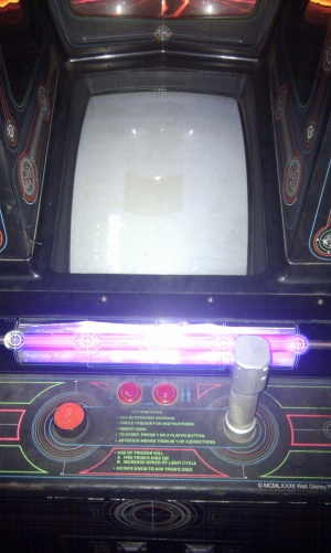
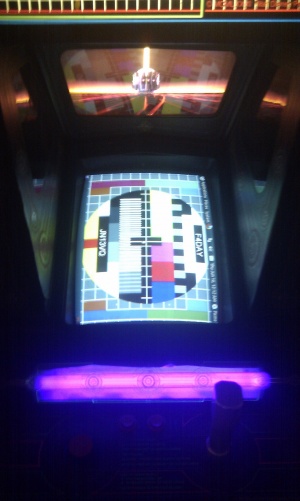
We salvaged a 1982 Tron arcade, of which the motherboard is fried. The goal is to make it work using a normal computer inside the tron and with the MAME emulator.
- The project code on Gitorious https://gitorious.org/tron-restore
Screen
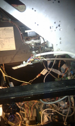
The first step was to connect the screen over VGA. The problem was that modern drivers did not regonized there was a screen connected. The fix is to put resistances on the 3 colors. An other problem was getting the right modeline for the screen and having a compatible graphic card.
Connection
FIXME: Schematic of the connection
Graphic Card
- Model: ATI Technologies Inc Radeon R200 QM [Radeon 9100]
- Driver: radeon
- File:Xorg.conf
Tips and Tricks
Something to add ?
Controls
- Using a Teensy board
- Using a [I-PAC]
- Wheel problematic
MAME
- Configuration
- Scripts
- Tips and Tricks
---
FIXME: Translate to english, better documentation of what we did, what problem we encountered
Description
Remettre en état la borne d'arcarde de Tron
A faire
- Démonter la borne
- Nettoyer et poncer la borne
- Repeindre
- Coller de nouveaux autocollants
-
Brancher un pc engine (ou autre) sur l'écran - Interfacer un pc avec les commandes de jeu => fait partielement
-
Faire marcher l'audio
Components
- Page de référence (Killer List Of Videogames)
- Wells Gardner 19K4906
- Autocollants originaux: http://www.arcadeoverlays.com/StoreFrontProfiles/deluxeSFshop.aspx?sfid=17232&c=0&search_text=tron&submit=GO
- Manette originale http://groovygamegear.com/webstore/index.php?main_page=product_info&products_id=319&zenid=6fa2e2c526f83c87ca941d4319b8dbdf
- Exemple de restauration: http://driph.com/words/tag/tron/
- Pour accepter la monnaie: CoinDoor
Moniteur
- Simulating the video out of the Tron board shows that it produces max 0.7V on a 75R output. This means that we should be able to use the VGA voltage levels directly without conversion.
- How to connect a PC to an arcade monitor.
- X11 Configuration
- Arcade VGA
- https://secure.wikimedia.org/wikipedia/en/wiki/VGA_connector
- Mire
To convince the video card that a monitor is present, you need a VGA dummy.
From [1]:
  8.10) Building a 5 BNC cable

This is straightforward, if time consuming and tedious.

The five coaxial cables (75 ohm, RG59 typical) are wired as shown in the
table.  The corresponding VGA connector pin numbers are in ().

     Coax Center         Coax Shield
  --------------------------------------
    Red Video  (1)      Red Return (6)
    Green Video  (2)    Green Return (7)
    Blue Video  (3)     Blue Return (8)
    H Sync (13)         Ground (5,10)
    V Sync (14)         Ground (5,10)

Tie pin 11 (ID0) to Ground to indicate a color monitor.
Leave pin 12 (ID1) open.

Make sure that the lengths of the cables are fairly well matched - to within
a couple of inches - to assure that the 3 color channels line up precisely.
(One foot of cable is about 1.5 to 2 ns of delay which is significant for
a 10 ns dot clock!).

Also note that you will lose your 'Plug-and-Play' capabilities without the
direct control connections to the monitor (or for monitors without these
features).

That's it!

You will wish that your fingers were about 10 times smaller than they are,
however. :-)
Controls
- http://www.usb.org/developers/devclass_docs/HID1_11.pdf
- http://www.usb.org/developers/devclass_docs/Hut1_12v2.pdf
- http://msdn.microsoft.com/en-us/windows/hardware/gg487464.aspx
- Desktop Page (0x1), Gampad (0x5), Hat switch.
Pictures
Personnes interessées
- Fred, JB, Simon, François
