Difference between revisions of "Extension Explorer 16"
(→Calculation) |
|||
| (22 intermediate revisions by the same user not shown) | |||
| Line 29: | Line 29: | ||
File:Lettre F.jpg | Fixme Display - lettre F - Orcad | File:Lettre F.jpg | Fixme Display - lettre F - Orcad | ||
File:Lettre_I.jpg | Fixme Display - lettre I - Orcad | File:Lettre_I.jpg | Fixme Display - lettre I - Orcad | ||
| + | File:Lettre X.jpg | Fixme Display - lettre X - Orcad | ||
| + | File:Lettre M.jpg | Fixme Display - lettre M - Orcad | ||
| + | File:Lettre E.jpg | Fixme Display - lettre E - Orcad | ||
</gallery> | </gallery> | ||
| Line 134: | Line 137: | ||
=== Datas === | === Datas === | ||
| − | * U_POW = 12V DC --> choice concerning the power supply of LED segments | + | * U_POW = Vcc = 12V DC --> choice concerning the power supply of LED segments |
| − | * U_LED = 2V DC | + | * U_LED = 2V DC --> voltage on once leds |
| − | * I_LED = 20mA | + | * U_SEG = 5*U_LED = 5*2V = 10V --> voltage on once segment |
| + | * I_LED = 20mA --> current use by once led | ||
=== Calculation === | === Calculation === | ||
==== Resistor in end line for vertical sgement ==== | ==== Resistor in end line for vertical sgement ==== | ||
if the segment is alone, the end line resistor is of (example each element of the X letter) : | if the segment is alone, the end line resistor is of (example each element of the X letter) : | ||
| + | |||
<math> | <math> | ||
R_{1Seg} = \frac{Vcc - U_{seg}}{I_{LED}} = \frac{12V - 10V}{20mA} | R_{1Seg} = \frac{Vcc - U_{seg}}{I_{LED}} = \frac{12V - 10V}{20mA} | ||
| Line 147: | Line 152: | ||
Power dissipated by the resistor Rseg: | Power dissipated by the resistor Rseg: | ||
| + | |||
<math> | <math> | ||
P_{R_{1Seg}} = R_{1Seg} \cdot I_{Led}^2 = 100 \cdot (20mA)^2 | P_{R_{1Seg}} = R_{1Seg} \cdot I_{Led}^2 = 100 \cdot (20mA)^2 | ||
| Line 155: | Line 161: | ||
if the segments are linked by two, the end line resistor is of (example for the F, I, M, E letters) : | if the segments are linked by two, the end line resistor is of (example for the F, I, M, E letters) : | ||
| + | |||
<math> | <math> | ||
R_{1Seg} = \frac{Vcc - U_{seg}}{I_{LED_{Seg1}} + I_{LED_{Seg2}}} = \frac{12V - 10V}{20mA + 20mA} | R_{1Seg} = \frac{Vcc - U_{seg}}{I_{LED_{Seg1}} + I_{LED_{Seg2}}} = \frac{12V - 10V}{20mA + 20mA} | ||
| Line 161: | Line 168: | ||
Power dissipated by the resistor Rseg: | Power dissipated by the resistor Rseg: | ||
| + | |||
<math> | <math> | ||
P_{R_{1Seg}} = R_{1Seg} \cdot (2*I_{Led})^2 = 100 \cdot (40mA)^2 | P_{R_{1Seg}} = R_{1Seg} \cdot (2*I_{Led})^2 = 100 \cdot (40mA)^2 | ||
| Line 170: | Line 178: | ||
==== Resistor in end line for horizontal sgement ==== | ==== Resistor in end line for horizontal sgement ==== | ||
if the segment is alone, the end line resistor is of (example each element of the M letter) : | if the segment is alone, the end line resistor is of (example each element of the M letter) : | ||
| + | |||
<math> | <math> | ||
R_{1LED} = \frac{Vcc - U_{seg_{LED}}}{I_{LED}} = \frac{12V - 2V}{20mA} | R_{1LED} = \frac{Vcc - U_{seg_{LED}}}{I_{LED}} = \frac{12V - 2V}{20mA} | ||
| Line 176: | Line 185: | ||
Power dissipated by the resistor R_LED: | Power dissipated by the resistor R_LED: | ||
| + | |||
<math> | <math> | ||
P_{R_{1LED}} = R_{1LED} \cdot I_{Led}^2 = 500 \cdot (20mA)^2 | P_{R_{1LED}} = R_{1LED} \cdot I_{Led}^2 = 500 \cdot (20mA)^2 | ||
| Line 184: | Line 194: | ||
if the segments are linked by two, the end line resistor is of (example for the F letter) : | if the segments are linked by two, the end line resistor is of (example for the F letter) : | ||
| + | |||
<math> | <math> | ||
R_{LEDs} = \frac{Vcc - U_{LED}}{I_{LED1} + I_{LED2}} = \frac{12V - 2V}{20mA + 20mA} | R_{LEDs} = \frac{Vcc - U_{LED}}{I_{LED1} + I_{LED2}} = \frac{12V - 2V}{20mA + 20mA} | ||
| Line 190: | Line 201: | ||
Power dissipated by the resistor RLED_2: | Power dissipated by the resistor RLED_2: | ||
| + | |||
<math> | <math> | ||
P_{R_{LEDs}} = R_{LEDs} \cdot (2*I_{Led})^2 = 250 \cdot (40mA)^2 | P_{R_{LEDs}} = R_{LEDs} \cdot (2*I_{Led})^2 = 250 \cdot (40mA)^2 | ||
| Line 198: | Line 210: | ||
if the segments are linked by three, the end line resistor is of (example for the E letter) : | if the segments are linked by three, the end line resistor is of (example for the E letter) : | ||
| + | |||
<math> | <math> | ||
R_{LEDs} = \frac{Vcc - U_{LED}}{I_{LED1} + I_{LED2} + I_{LED3}} = \frac{12V - 2V}{20mA + 20mA +20mA} | R_{LEDs} = \frac{Vcc - U_{LED}}{I_{LED1} + I_{LED2} + I_{LED3}} = \frac{12V - 2V}{20mA + 20mA +20mA} | ||
| Line 204: | Line 217: | ||
Power dissipated by the resistor RLED_3: | Power dissipated by the resistor RLED_3: | ||
| + | |||
<math> | <math> | ||
P_{R_{LEDs}} = R_{LEDs} \cdot (3*I_{Led})^2 = 250 \cdot (60mA)^2 | P_{R_{LEDs}} = R_{LEDs} \cdot (3*I_{Led})^2 = 250 \cdot (60mA)^2 | ||
| Line 220: | Line 234: | ||
== Cross Fire Part == | == Cross Fire Part == | ||
| − | {| class=" | + | {| class="wikitable" style="text-align:center;" |
|+ BOM for the Feux Tricolor | |+ BOM for the Feux Tricolor | ||
|- | |- | ||
| Line 304: | Line 318: | ||
== LED DISPLAY FIXME == | == LED DISPLAY FIXME == | ||
| − | {| class=" | + | {| class="wikitable" style="text-align:center;" |
| − | |+ BOM for the | + | |+ BOM for the FIXME Display |
|- | |- | ||
! scope="col" | Designation | ! scope="col" | Designation | ||
| + | ! scope="col" | Type de boitier | ||
! scope="col" | Nb de composants | ! scope="col" | Nb de composants | ||
! scope="col" | Fournisseur | ! scope="col" | Fournisseur | ||
| Line 314: | Line 329: | ||
|- | |- | ||
| MULTI LEDS (5 led par boitier) L-132CB | | MULTI LEDS (5 led par boitier) L-132CB | ||
| + | | 35mm x 6.1mm | ||
| 21 | | 21 | ||
| Farnell | | Farnell | ||
| Line 319: | Line 335: | ||
| 3.75 CHF/pieces | | 3.75 CHF/pieces | ||
|- | |- | ||
| − | | | + | | DEMULTIPLEXEUR SIMPLE - CBT3251PW |
| + | | TSSOP-16 | ||
| + | | 4 | ||
| + | | Farnell | ||
| + | | 2445292 | ||
| + | | 0.2 CHF/pieces | ||
|- | |- | ||
| − | + | | Transistor MOSFET - FDD3N40TM | |
| + | | TO-252AA | ||
| + | | 29 | ||
| + | | Farnell | ||
| + | | 2453399 | ||
| + | | 0.6 CHF/pieces | ||
|- | |- | ||
| − | + | | Connecteur BASSE TENSION - MJ-179PH | |
| + | | - | ||
| + | | 1 | ||
| + | | Farnell | ||
| + | | 1737246 | ||
| + | | 1.2 CHF/pieces | ||
|- | |- | ||
| − | + | | Condensateur SMD 100nF/16V - CC0805KRX7R7BB104 | |
| + | | 0805 | ||
| + | | 4 | ||
| + | | Farnell | ||
| + | | 644160 | ||
| + | | 0.45 CHF/10x pieces min | ||
|- | |- | ||
| − | + | | Resistance SMD 51o/1/4W - WR12X51R0FTL | |
| + | | 1206 | ||
| + | | 5 | ||
| + | | Farnell | ||
| + | | 2502655 | ||
| + | | 0.25 CHF/50x pieces min | ||
|- | |- | ||
| − | + | | Resistance SMD 270o/1/2W - ERJP6WF2700V | |
| + | | 0805 | ||
| + | | 5 | ||
| + | | Farnell | ||
| + | | 2253894 | ||
| + | | 0.70 CHF/5x pieces min | ||
|- | |- | ||
| − | + | | Resistance SMD 100o/1/4W - ERJP6WF2700V | |
| + | | 0805 | ||
| + | | 4 | ||
| + | | Farnell | ||
| + | | 2502669 | ||
| + | | 0.30 CHF/100x pieces min | ||
|- | |- | ||
| − | + | | Resistance SMD 510o/1/4W - WR08X5100FTL | |
| + | | 0805 | ||
| + | | 10 | ||
| + | | Farnell | ||
| + | | 2502738 | ||
| + | | 0.30 CHF/100x pieces min | ||
|- | |- | ||
| − | + | | Resistance SMD 180o/1W - ERJB1AF181U | |
| + | | 2010 | ||
| + | | 5 | ||
| + | | Farnell | ||
| + | | 2293954RL | ||
| + | | 0.45 CHF/150x pieces min | ||
|- | |- | ||
| − | + | | Diode 20V/2A - PMEG2010EA | |
| − | |- | + | | SOD-323 |
| − | + | | 1 | |
| + | | Farnell | ||
| + | | 2319120 | ||
| + | | 0.2 CHF | ||
|} | |} | ||
| − | |||
| − | |||
= Assembly = | = Assembly = | ||
| Line 367: | Line 429: | ||
* datasheet on DEMUX 1:8 -> NXP -> CBT3251 [[File:CBT3251.pdf]] | * datasheet on DEMUX 1:8 -> NXP -> CBT3251 [[File:CBT3251.pdf]] | ||
* datasheet on MOSFET Canal P -> Faishild -> FDD3N40 [[File:MOSFET_P_FDD3N40.pdf]] | * datasheet on MOSFET Canal P -> Faishild -> FDD3N40 [[File:MOSFET_P_FDD3N40.pdf]] | ||
| − | * datasheet on | + | * datasheet on the LED Barre -> OPTO IMAGE -> L-132CB ou BA0520HR5A [[File:LED L-132CB.pdf]] |
| + | * datasheet on Diode -> NXP -> PMEG2010EA,115 [[File:Diode.pdf]] | ||
== required links == | == required links == | ||
Latest revision as of 15:20, 14 December 2015
Contents
Description
In French: Création d'une carte d'extension pour la carte Explorer (PROJET: Carte Explorer 16 & Exos sur les uC).
- V1: un montage permettra de simuler un carrefour routier, composer de 4 feux (RGB)
- V2: montage permettant d'allumer séquentiellement des leds pour afficher le nom de FIXME
in English:
creation of one extansion board for the Explorer Board (see the links above)
- V1: assembly will allow to simulate a crossroad (4 fires (RGB))
- V2: assembly allowing to display sequentially the leds to screen FIXME
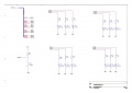
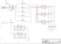
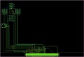
Digram - Schematic
Cross Light Part
Schema Feux Tricolores - Kicad
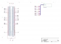
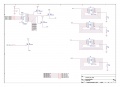
bloc H1 - General - Orcad
bloc H2 - Cross Light part - Orcad


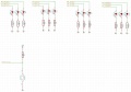
LEDS DISPLAY FIXME
Fixme Display - lettre F - Orcad
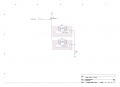
Fixme Display - lettre I - Orcad
Fixme Display - lettre X - Orcad

Fixme Display - lettre M - Orcad
Fixme Display - lettre E - Orcad


Part Calculation of Electronics Digram
LED's for crossroad
- the datasheet of the DSP implemented on the Explorer Board 16 (see pages 1 & 273) indicates that :
- output current of I/O : I = 10mA
- voltage I/O : VDD = 3.3V
- the datasheet of the red LED (see pages 3) indicates that :
- conduction voltage : ULR = VF = 1.8V
- average current : I = 20mA
- the datasheet of the orange LED (see pages 3 / 4 / 5) indicates that :
- conduction voltage : ULO = VF = 1.9V
- average current : I = 30mA
- the datasheet of the green LED (see pages 3 / 4 / 5) indicates that :
- conduction voltage : ULG = VF = 2.2V
- average current : I = 30mA
Formula
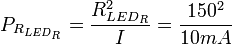
- calculation of resistance R_LED_R :
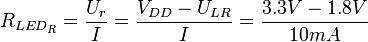 = 150 Ω
- power dispersed by the resistance P_R_LED_R :
 = 15 mW
- calculation of resistance R_LED_O :
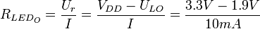 = 140 Ω
- power dispersed by the resistance P_R_LED_O :
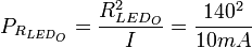 = 14 mW
- calculation of resistance R_LED_G :
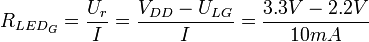 = 110 Ω
- power dispersed by the resistance P_R_LED_G :
 = 11 mW
Switch for crossroad
- the datasheet of the DSP implemented on the Explorer Board 16 (see pages 1, 278, 279) indicates that :
- output current of I/O : I_output = 10mA
- input current of I/O : I_output max = 5mA
- voltage I/O : VDD = 3.3V
- leakage current of I/O : 2uA
- low state ('0') in voltage : 0,2 * VDD
Formula
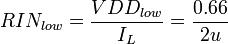
- voltage seens by the input of uC when it's a low state VDD_low :
 = 0.66 V
- Resitor seens by the input of uC when it's a low state RIN_low :
 = 330 kΩ
- Resitor Pull-Up MAX :
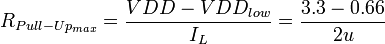 = 1.32 MΩ
Remark : the resistor must be more less that the R_PULL-UP_max - usually, the value of 10kohm is using for the resistor pull-up.
- Current using when the switch is closed
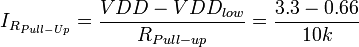 = 264 uA
- power dispersed by the resistance push-pull when the switch is actived
 = 696.96 uW
LEDS For DSIPLAY FIXME
Details arround the LED Segment
In French : pour cette partie du projet, le choix s'est porté sur des multi leds de type L-132CB, le but est que tous les segments verticaux s'allument en meme temps et tous les leds horizontales s'allume une après l'autre. Pour les segments verticaux, si on chaîne les 5 leds du segment (série), on obtient du 10V sur les 5 leds... donc il faut prévoir pour le montage une alimentation 12V DC qui tienne 1A au minimum. Pour les segments horizontaux, c'est qu'une led par segment qui sera alimenté -> 2V par led.
IN English: For this part of the project, the choice was carried on the multi LED L-132CB, the goal is that all vertical segment display in same time ans the horizontal leds display one after the others. For the vertical sgment, the leds will be chained in serial (5 leds -> 10V). For this assembly to provide for the power, a voltage of 12V. For the horizontal segment, there will have only 1 led supplied (2V).
to see more details, check the schematics part !!!
Datas
- U_POW = Vcc = 12V DC --> choice concerning the power supply of LED segments
- U_LED = 2V DC --> voltage on once leds
- U_SEG = 5*U_LED = 5*2V = 10V --> voltage on once segment
- I_LED = 20mA --> current use by once led
Calculation
Resistor in end line for vertical sgement
if the segment is alone, the end line resistor is of (example each element of the X letter) :
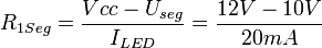 = 100 Ω
Power dissipated by the resistor Rseg:
 = 40 mW
The choice for the resistor(s) value is : 100 Ω 1/4W
if the segments are linked by two, the end line resistor is of (example for the F, I, M, E letters) :
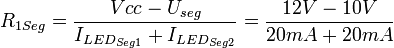 = 50 Ω
Power dissipated by the resistor Rseg:
 = 80 mW
The choice for the resistor(s) value is : 51 Ω 1/4W
Resistor in end line for horizontal sgement
if the segment is alone, the end line resistor is of (example each element of the M letter) :
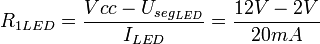 = 500 Ω
Power dissipated by the resistor R_LED:
 = 200 mW
The choice for the resistor(s) value is : 510 Ω 1/4W
if the segments are linked by two, the end line resistor is of (example for the F letter) :
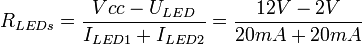 = 250 Ω
Power dissipated by the resistor RLED_2:
 = 400 mW
The choice for the resistor(s) value is : 270 Ω 1/2W
if the segments are linked by three, the end line resistor is of (example for the E letter) :
 = 167 Ω
Power dissipated by the resistor RLED_3:
 = 601,2 mW
The choice for the resistor(s) value is : 180 Ω 1W
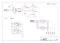
Layout
Extension Explorer 16 - cross fire - PCB Feux Tricolores - Kicad
H1 Cross Light - Layout - Orcad


BOM - Bill of Material
Cross Fire Part
| Designation | Nb de composants | Fournisseur | Référence | Prix |
|---|---|---|---|---|
| Led Rouge 5mm | 4 | Farnell | 2112111 | 0.307 CHFrs /pieces |
| Led Rouge SMD (option) | 4 | Farnell | 8554641 | 0.0982 CHFrs /5pieces |
| Led Orange 5mm | 4 | Farnell | 1003212 | 0.257 CHFrs /pieces |
| Led Orange SMD (option) | 4 | Farnell | 8554552 | 0.537 CHFrs /5pieces |
| Led Verte 5mm | 4 | Farnell | 2217954 | 0.368 CHFrs /pieces |
| Led Verte SMD (option) | 4 | Farnell | 8554609 | 0.326 CHFrs /5pieces |
| Resistance SMD 110 ohm 100mW | 4 | Farnell | 2351021 | 0.01 CHFrs /pieces |
| Resistance SMD 140 ohm 100mW | 4 | Farnell | 2351049 | 0.01 CHFrs /pieces |
| Resistance SMD 150 ohm 100mW | 4 | Farnell | 9332596 | 0.0734 CHFrs / 50pieces |
| Resistance SMD 10kohm 100mW | 4 | Farnell | 9332391 | 0.082 CHFrs / 50pieces |
| Commutateur Tactile | 1 | Farnell | 1555985 | 0.155 CHFrs /pieces |
| Connecteur 120pin | 1 | Digikey | MEC1-160-02-S-D-A or MEC1-160-02-F-DEM2 | 9.3 $/pieces |
LED DISPLAY FIXME
| Designation | Type de boitier | Nb de composants | Fournisseur | Référence | Prix |
|---|---|---|---|---|---|
| MULTI LEDS (5 led par boitier) L-132CB | 35mm x 6.1mm | 21 | Farnell | 1208841 | 3.75 CHF/pieces |
| DEMULTIPLEXEUR SIMPLE - CBT3251PW | TSSOP-16 | 4 | Farnell | 2445292 | 0.2 CHF/pieces |
| Transistor MOSFET - FDD3N40TM | TO-252AA | 29 | Farnell | 2453399 | 0.6 CHF/pieces |
| Connecteur BASSE TENSION - MJ-179PH | - | 1 | Farnell | 1737246 | 1.2 CHF/pieces |
| Condensateur SMD 100nF/16V - CC0805KRX7R7BB104 | 0805 | 4 | Farnell | 644160 | 0.45 CHF/10x pieces min |
| Resistance SMD 51o/1/4W - WR12X51R0FTL | 1206 | 5 | Farnell | 2502655 | 0.25 CHF/50x pieces min |
| Resistance SMD 270o/1/2W - ERJP6WF2700V | 0805 | 5 | Farnell | 2253894 | 0.70 CHF/5x pieces min |
| Resistance SMD 100o/1/4W - ERJP6WF2700V | 0805 | 4 | Farnell | 2502669 | 0.30 CHF/100x pieces min |
| Resistance SMD 510o/1/4W - WR08X5100FTL | 0805 | 10 | Farnell | 2502738 | 0.30 CHF/100x pieces min |
| Resistance SMD 180o/1W - ERJB1AF181U | 2010 | 5 | Farnell | 2293954RL | 0.45 CHF/150x pieces min |
| Diode 20V/2A - PMEG2010EA | SOD-323 | 1 | Farnell | 2319120 | 0.2 CHF |
Assembly
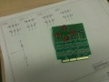
montage en VerroBoard Feux Tricolores

Tests
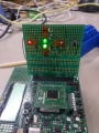
Test Feux Tricolores -> feux rouges
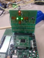
Test Feux Tricolores -> feux verts


Modification
Documentation
PDF FILE
- datasheet on the RED/ORANGE/GREEN LED -> AVAGO File:LED RED.pdf
- datasheet on the RED/ORANGE/GREEN LED SMD -> AVAGO File:LED SMD.pdf
- datasheet of one touch commande (microswitch tactile) -> ALCOSWITCH File:Microswitch.pdf
- datasheet on DEMUX 1:8 -> NXP -> CBT3251 File:CBT3251.pdf
- datasheet on MOSFET Canal P -> Faishild -> FDD3N40 File:MOSFET P FDD3N40.pdf
- datasheet on the LED Barre -> OPTO IMAGE -> L-132CB ou BA0520HR5A File:LED L-132CB.pdf
- datasheet on Diode -> NXP -> PMEG2010EA,115 File:Diode.pdf
required links
- explication sur le calcul d'une résistance Push Pull
- Doc PDF Datasheet DSPIC33FJxxx
- Doc PDF Carte Explorer 16
- wiki sur les transistors MOSFET
Contributor
- User:Philoux
- You !!??!!