Difference between revisions of "Full adder"
From Fixme.ch
| Line 14: | Line 14: | ||
[[File:Adderlogic.gif]] | [[File:Adderlogic.gif]] | ||
| − | From this chip, we | + | From this chip, we will make an half adder. It is one of the basic component of every CPU as it is adding two bits. It's use is to have two bits. They represent a state either 1 or 0. We will add them with the following scheme : |
<pre> | <pre> | ||
1 + 1 = 10 | 1 + 1 = 10 | ||
| Line 25: | Line 25: | ||
^ this bit is the least significant bit. We call it C0 later on. | ^ this bit is the least significant bit. We call it C0 later on. | ||
</pre> | </pre> | ||
| − | Just follow the | + | Just follow the schema. You will need two chip to implement the half adder. |
[[File:Halfadder.gif]] | [[File:Halfadder.gif]] | ||
== What is happening there ? == | == What is happening there ? == | ||
Revision as of 23:57, 14 May 2012
Goal
- First step into logic
Level
- Knowing how to use a breadboard
Component
- Only one logic gate array.
How to
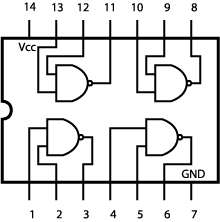
The logic circuit of the chip is as followed :
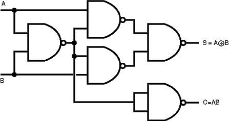
From this chip, we will make an half adder. It is one of the basic component of every CPU as it is adding two bits. It's use is to have two bits. They represent a state either 1 or 0. We will add them with the following scheme :
1 + 1 = 10
1 + 0 = 01
0 + 1 = 01
0 + 0 = 00
^ this bit is the first bit we add, we will call it A later on.
    ^ this bit is the second bit we add, we will call it B later on.
        ^ this bit is the most significant bit. We call it C1 later on.
         ^ this bit is the least significant bit. We call it C0 later on.
Just follow the schema. You will need two chip to implement the half adder.

