Difference between revisions of "Extension Explorer 16"
From Fixme.ch
(→Digram - Schematic) |
(→Cross Light Part) |
||
| Line 14: | Line 14: | ||
= Digram - Schematic = | = Digram - Schematic = | ||
== Cross Light Part == | == Cross Light Part == | ||
| − | [[File:Schema feux.JPG| | + | [[File:Schema feux.JPG|800px|alt=schema de la partie Feux tricolores|Schema Feux Tricolores]] |
= Part Calculation of Electronics Digram = | = Part Calculation of Electronics Digram = | ||
Revision as of 00:12, 1 November 2014
Contents
Description
In French: Création d'une carte d'extension pour la carte Explorer (PROJET: Carte Explorer 16 & Exos sur les uC).
- V1: un montage permettra de simuler un carrefour routier, composer de 4 feux (RGB)
in English:
creation of one extansion board for the Explorer Board (see the links above)
- V1: assembly will allow to simulate a crossroad (4 fires (RGB))
Digram - Schematic
Cross Light Part

Part Calculation of Electronics Digram
LED's for crossroad
- the datasheet of the DSP implemented on the Explorer Board 16 (see pages 1 & 273) indicates that :
- output current of I/O : I = 10mA
- voltage I/O : VDD = 3.3V
- the datasheet of the red LED (see pages 3) indicates that :
- conduction voltage : ULR = VF = 1.8V
- average current : I = 20mA
- the datasheet of the orange LED (see pages 3 / 4 / 5) indicates that :
- conduction voltage : ULO = VF = 1.9V
- average current : I = 30mA
- the datasheet of the green LED (see pages 3 / 4 / 5) indicates that :
- conduction voltage : ULG = VF = 2.2V
- average current : I = 30mA
Formula
- calculation of resistance R_LED_R :
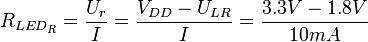 = 150 ohm
- power dispersed by the resistance P_R_LED_R :
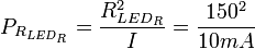 = 15 mW
- calculation of resistance R_LED_O :
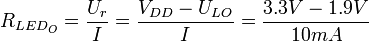 = 140 ohm
- power dispersed by the resistance P_R_LED_O :
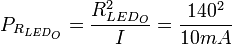 = 14 mW
- calculation of resistance R_LED_G :
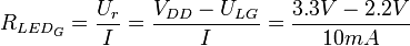 = 110 ohm
- power dispersed by the resistance P_R_LED_G :
 = 11 mW
Switch for crossroad
- the datasheet of the DSP implemented on the Explorer Board 16 (see pages 1, 278, 279) indicates that :
- output current of I/O : I_output = 10mA
- input current of I/O : I_output max = 5mA
- voltage I/O : VDD = 3.3V
- leakage current of I/O : 2uA
- low state ('0') in voltage : 0,2 * VDD
Formula
- voltage seens by the input of uC when it's a low state VDD_low :
 = 0.66 V
- Resitor seens by the input of uC when it's a low state RIN_low :
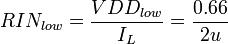 = 330 kohms
- Resitor Pull-Up MAX :
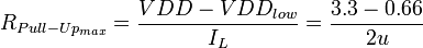 = 1.32 Mohms
Remark : the resistor must be more less that the R_PULL-UP_max - usually, the value of 10kohm is using for the resistor pull-up.
- Current using when the switch is closed
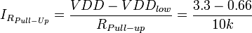 = 264 uA
Layout
Components listing
Modification
Documentation
PDF FILE
- datasheet on the RED LED - AVAGO File:LED RED.pdf