Difference between revisions of "DVPWM"
m |
m (merge commentaires Jo) |
||
| Line 1: | Line 1: | ||
| − | + | DVPWM is a PWM driver/dimmer originally designed for very simple LED lighting. It is built to be small, robust and convenient. | |
| − | + | It has one single control: a rotating knob with on/off switch attached. In "off" position, the circuitry is completely offline. | |
| − | + | * '''Input''': 6-15 VDC. With input voltage polarity inversion protection, suitable for dirty or noisy power supplies | |
| − | + | * '''Output''': "high" frequency [? kHz] PWM with duty cycle ranging from almost zero to almost 100% | |
| − | * '''Input''': 6-15 VDC. | + | * '''Maximum admissible current''': 5A with SMD fuse on-board. This makes it probably overkill for small lighting, but will allow you to power about 25m of standard LED stripe or even small electric motors because there is a beefy free wheel diode protection. |
| − | * '''Output''': "high" frequency [? kHz] PWM with duty cycle ranging from almost zero to almost 100% | + | * In most cases, more than one DVPWM can be combined for RGB lighting ('''common ground''') |
| − | * '''Maximum admissible current''': 5A with SMD fuse on-board. This makes it probably overkill for small lighting, but will allow you to power about 25m of standard LED stripe or even small electric motors | + | |
| − | * In most cases, more than one DVPWM can be combined for RGB lighting ('''common ground''') | + | |
== Schematic == | == Schematic == | ||
| − | Thanks to Joël H for the schematic. He made it with Kicad and his little brain [I | + | Thanks to Joël H for the schematic. He made it with Kicad and his little brain [I may have a relationship with Homer Simpson, who is actually my idol -Jo] |
[[Media:DVPWM Schematic.pdf|Schematic (PDF)]] | [[Media:DVPWM Schematic.pdf|Schematic (PDF)]] | ||
| Line 19: | Line 17: | ||
[[File:DVPWM render bottom.png|200px|thumb|right|PCB bottom view]] | [[File:DVPWM render bottom.png|200px|thumb|right|PCB bottom view]] | ||
| − | PCB design was achieved with [http://eda.eremex.com/products/topor/ Topor], a piece of software which truly amazes me. Through recursive contemplation of the routing algorithm, I was able to shorten the track lengths to an almost minimum and reduce the number of vias to | + | PCB design was achieved with [http://eda.eremex.com/products/topor/ Topor], a piece of software which truly amazes me. Through recursive contemplation of the routing algorithm, I was able to shorten the track lengths to an almost minimum and reduce the number of vias to an absolute minimum [zero !!!]. The output from Topor was then imported into Kicad again, because we couldn't be bothered to learn new things so early after sunrise. |
PCB size is 26x37mm. Height from frontplate (if applicable: circuit secured to frontplate using the knob's nut): 22mm | PCB size is 26x37mm. Height from frontplate (if applicable: circuit secured to frontplate using the knob's nut): 22mm | ||
Revision as of 14:17, 23 October 2014
DVPWM is a PWM driver/dimmer originally designed for very simple LED lighting. It is built to be small, robust and convenient.
It has one single control: a rotating knob with on/off switch attached. In "off" position, the circuitry is completely offline.
- Input: 6-15 VDC. With input voltage polarity inversion protection, suitable for dirty or noisy power supplies
- Output: "high" frequency [? kHz] PWM with duty cycle ranging from almost zero to almost 100%
- Maximum admissible current: 5A with SMD fuse on-board. This makes it probably overkill for small lighting, but will allow you to power about 25m of standard LED stripe or even small electric motors because there is a beefy free wheel diode protection.
- In most cases, more than one DVPWM can be combined for RGB lighting (common ground)
Contents
Schematic
Thanks to Joël H for the schematic. He made it with Kicad and his little brain [I may have a relationship with Homer Simpson, who is actually my idol -Jo]
PCB
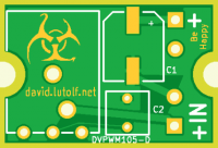
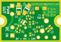
PCB design was achieved with Topor, a piece of software which truly amazes me. Through recursive contemplation of the routing algorithm, I was able to shorten the track lengths to an almost minimum and reduce the number of vias to an absolute minimum [zero !!!]. The output from Topor was then imported into Kicad again, because we couldn't be bothered to learn new things so early after sunrise.
PCB size is 26x37mm. Height from frontplate (if applicable: circuit secured to frontplate using the knob's nut): 22mm
Most text is made unreadable when the components are in place, but we didn't care much about this ; priority was the size, and it was time for a nap.
Component list
To achieve the very small size, most components are SMD type. Only exceptions are the rotating knob, and one capacitor. Due to the relatively small amount of components and their size, this circuit is an ideal for anyone who would like to learn SMD soldering.
Suggestions for cheaper alternates are welcome.
Kits
Kits are available for CHF 30.- a piece, cheaper for larger quantities. This includes the PCB and all the necessary components. While this may seem relatively expensive, the knob is far from cheap (and no alternative was found at the time) and so is one of the capacitors. There is also some provision for development costs, so we can continue to offer you more useful circuits.
Please contact electro-shop@pg21.org to order.

