Difference between revisions of "Old makerspace laser cutter"
(→Usage: extended laserworks usage instructions) |
|||
| Line 1: | Line 1: | ||
== Usage == | == Usage == | ||
| − | # '''Prepare your file to cut or engrave'''. You'll need a .dxf file with all the paths stroked at 0.25px, with each different color of the paths representing | + | # '''Prepare your file to cut or engrave'''. You'll need a .dxf file with all the paths stroked at 0.25px, with each different color of the paths representing different cut/engrave parameters. You can find such files by searching on [https://www.thingiverse.com/search?q=laser+cut&sa= Thingiverse] and other related sites, or creating your own with software such as [[#Inkscape|Inkscape]], [[#Illustrator|Illustrator]], [[#Inventor|Inventor]], or many others. Unfortunately many of the files you find online are in .ai, .pdf or .svg, you'll need to open them in one of these apps and export them to .dxf. |
| − | # '''Open the file in Laserworks'''. On the machine next to the laser cutter, plug in your USB key, and then import the .dxf via File > Import (ctr + i). If | + | # '''Open the file in Laserworks'''. On the machine next to the laser cutter, plug in your USB key, and then import the .dxf via File > Import (ctr + i). If Laserworks says that it did not find any data, it means that you did not format your file correctly, or you used an incompatible file type. |
| − | # '''Scale and arrange your paths'''. Once you have imported your .dxf, the paths in the file will be shown in Laserworks. You can either select all of the | + | # '''Scale and arrange your paths'''. Once you have imported your .dxf, the paths in the file will be shown in Laserworks. You can either select all of the paths, or select just one of them, and scale using the black arrows on the sides, or by changing the values in the scale toolbar on the top. It is also possible to move your paths by clicking and dragging the pink cross in the middle. You can group your paths using the group button on the top toolbar. |
| + | # '''Add or edit paths'''. You can do some basics edits in Laserworks with the toolbar on the left. If you want to cut/engrave your paths with different settings, you can set each paths' parameters by choosing a colour on the bottom toolbar. For example: you want to engrave a design, and cut a circle around it - so you set the design to red, and the circle to black. | ||
| + | # '''Select your engrave/cut parameters'''. On the top of the toolbar on the right, you'll see that each colour has its own parameters, and you can edit each one by double-clicking on it. | ||
| + | ## '''Output''' Set to yes in order for your paths to cut/engrave (setting it to no could be useful if you have construction/instructional paths or you have multiple designs in the same file). | ||
| + | ## '''Speed'''. See [[#Materials|Materials]] section below to select the correct speed for cutting. | ||
| + | ## '''Blowing'''. Set to yes, this is the internal air compressor that blows out of the cutting head. | ||
| + | ## '''Processing mode'''. <u>Set this first</u> as all the following settings will depend on it. ''Cut'' will cut along the paths as a vector, ''scan'' will engrave between the lines of your paths, and ''dot'' will make a dotted outline of your paths. | ||
| + | ## '''Power'''. See [[#Materials|Materials]] section below to select the correct power. | ||
| + | ## '''Scan mode'''. ''Only in scanning/engraving mode''. Unilaterism mode will scan/engrave one line at each time the laser head passes, and swing mode will scan/engrave two lines at each pass, going in both directions. Uni mode gives better results but takes twice as long as swing mode. Set x if the paths are wider on the x scale than on the y scale, and choose y for when the paths are longer on the y scale - this optimises laser time. | ||
| + | ## '''Interval'''. ''Only in scanning/engraving mode''. Set the distance between each laser pass. 0.1mm is the minimum distance, and will produce results similar to a printer - but it takes a lot of time. 0.2mm is a good average, you can't really see the space between the passes. You can go up to 0.4mm before it starts to be somewhat visible. | ||
| + | |||
* Always cut with lid closed | * Always cut with lid closed | ||
Revision as of 02:33, 1 May 2015
Contents
Usage
- Prepare your file to cut or engrave. You'll need a .dxf file with all the paths stroked at 0.25px, with each different color of the paths representing different cut/engrave parameters. You can find such files by searching on Thingiverse and other related sites, or creating your own with software such as Inkscape, Illustrator, Inventor, or many others. Unfortunately many of the files you find online are in .ai, .pdf or .svg, you'll need to open them in one of these apps and export them to .dxf.
- Open the file in Laserworks. On the machine next to the laser cutter, plug in your USB key, and then import the .dxf via File > Import (ctr + i). If Laserworks says that it did not find any data, it means that you did not format your file correctly, or you used an incompatible file type.
- Scale and arrange your paths. Once you have imported your .dxf, the paths in the file will be shown in Laserworks. You can either select all of the paths, or select just one of them, and scale using the black arrows on the sides, or by changing the values in the scale toolbar on the top. It is also possible to move your paths by clicking and dragging the pink cross in the middle. You can group your paths using the group button on the top toolbar.
- Add or edit paths. You can do some basics edits in Laserworks with the toolbar on the left. If you want to cut/engrave your paths with different settings, you can set each paths' parameters by choosing a colour on the bottom toolbar. For example: you want to engrave a design, and cut a circle around it - so you set the design to red, and the circle to black.
- Select your engrave/cut parameters. On the top of the toolbar on the right, you'll see that each colour has its own parameters, and you can edit each one by double-clicking on it.
- Output Set to yes in order for your paths to cut/engrave (setting it to no could be useful if you have construction/instructional paths or you have multiple designs in the same file).
- Speed. See Materials section below to select the correct speed for cutting.
- Blowing. Set to yes, this is the internal air compressor that blows out of the cutting head.
- Processing mode. Set this first as all the following settings will depend on it. Cut will cut along the paths as a vector, scan will engrave between the lines of your paths, and dot will make a dotted outline of your paths.
- Power. See Materials section below to select the correct power.
- Scan mode. Only in scanning/engraving mode. Unilaterism mode will scan/engrave one line at each time the laser head passes, and swing mode will scan/engrave two lines at each pass, going in both directions. Uni mode gives better results but takes twice as long as swing mode. Set x if the paths are wider on the x scale than on the y scale, and choose y for when the paths are longer on the y scale - this optimises laser time.
- Interval. Only in scanning/engraving mode. Set the distance between each laser pass. 0.1mm is the minimum distance, and will produce results similar to a printer - but it takes a lot of time. 0.2mm is a good average, you can't really see the space between the passes. You can go up to 0.4mm before it starts to be somewhat visible.
- Always cut with lid closed
- Always wear safety goggles
- Do not leave the laser cutter cutting without supervision
- Always cut with the ventilation system on (black power strip under laser cutter)
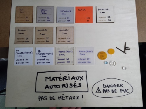
- Only use materials that are laser safe - see list below (TL;DR: never use PVC, don't cut metal)
- Be careful whilst using the control panel or the software to not start the laser by accident
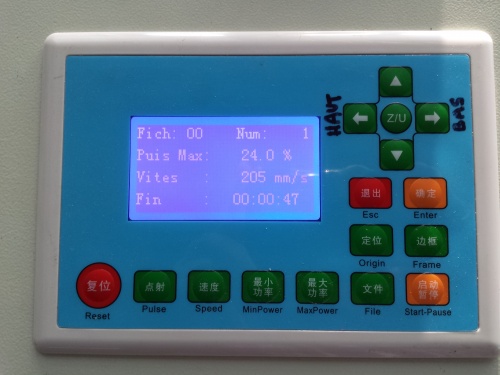
- Be careful of the Pulse and Start-Pause buttons on laser cutter
- Be careful of the Start button on laser cutter software (particularly when resuming from standby..)
This section is work in progress
Design software
Inkscape
- Make sure object is vector (if you import a svg or make your own drawing, it will be already a vector; however png's and jpg's aren't vectors)
- Select object, then open the Trace Bitmap menu (Path > Trace Bitmap)
- Play with the various single scan options, and click 'update' to see a preview
- Convert the object to a path (Path > Object to Path)
- Set stroke (Object > Fill and Stroke) of object to 0.25px and no fill
- For every different layer you want to cut/engrave on the laser (aka engraved with different power for gradients), you must create a new color of the stroke
- Save as as dxf (you need python-lxml for this part, apt-get install python-lxml or pip install lxml (doesn't work out of the box on mac))
Illustrator
Basic instructions
- Getting started with Illustrator
- Make sure that all the things you want to cut/engrave are paths with a 0.25mm stroke and no fill
- Place all the paths into the root of a layer - Laserworks does not recognise sublayers, linked files or grouped paths
- Each color you select for your paths will show up as a different settings layer in Laserworks (e.g. black lines can be set to cut, red lines set to engrave). Any layers in Illustrator will be merged.
- File > Export as dxf, use R13/LT95 for the dxf format. Laserworks also supportes .ai files saved as Illustrator 8, but you may loose some editing functionality when saving with this, so be careful.
Text
- Select your text and remove the fill, then set a stroke of 0.25
- You must expand the text before importing it into Laserworks:
- When saving as dxf, select Outline Text
- Select text, then click Object > Expand. This will not allow you to edit the text afterwards, but works when saving as .ai
Bitmaps and images
- Drag your image into illustrator, and click on Image Trace (use the arrow on the right to find the best settings, or press the settings button to custom set the settings)
- Click the expand button
Rhino
Used by Swisskoo and marc
Autodesk Inventor
Used by Swisskoo and User:Nemen
Export to .dxf
- Right-click on the face of your part you want to export.
- Choose "Export face as"
- Type the filename and click on Save
Laser software
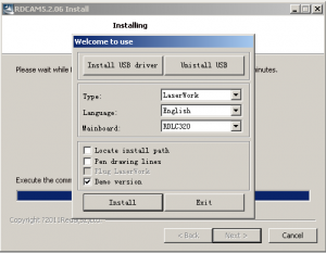
The laser cutter is controlled by RDCam (version 5.2.06 installed on Atelier computer, other versions available on foo), it's manual is here File:Rdcam manual.pdf. When installing, you have to install it in 'demo mode', otherwise Laserworks won't open without a cutter connected (also don't forget to select english ;).
RDCam would not install in crossover (gui for wine), but feel free to try. Please note that .rld files created in different versions of the software are not inter-compatible unfortunately. This guy started reverse engineering the (scrambled) communications and .rld protocols, he has also managed to get it to work on wine.
Materials
Wood
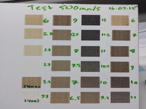
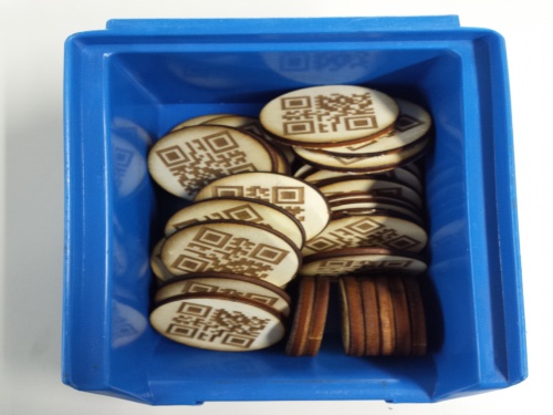
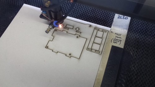
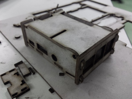
4mm wood - 28-45mm/s @ 100% for cutting, depending on location on laser bed. 35 is a good average. Engraving is good at 500mm/s, you can engrave from 6% to 30-50-60% ish - this needs to be further clarified. 15-20% with a 0.2 interval gives a good clean result.
6mm wood - 20-30mm/s
Cardboard
40mm/s
Paper
No testing done yet
Acrylic
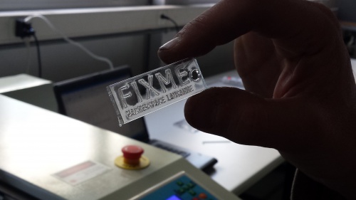
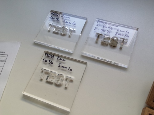
8-20mm/s, engraving at 20% 500mm/s
Others
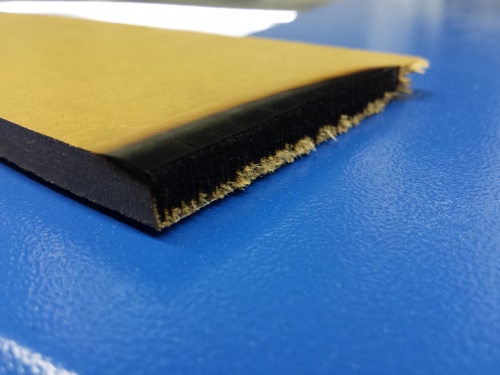
There still needs to be extensive testing done to see which materials work and which don't, but basically the gist of it is: don't use anything that has PVC in it, and don't use metal (unless for engraving -> need to explore options). There have been some tests with rubber (for stamps) as well, this needs to be properly documented and more testing needs to be done.
Hardware
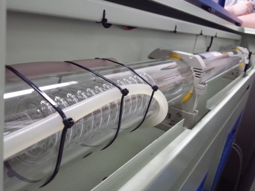
Search terms: Ebay 100w laser or just 100w laser - it's a generic design (3500~4000 usd for laser cutter with/without shipping depending on source, ~1000 usd for laser tube with shipping). RD-ACS controller (generic controller so used in lots of laser cutters).
Photos
Wood
Cardboard
Acrylic
Others
